All the equipment of the system is grounded through the earth electrode. Unhindered earthing protects electrical equipment and personnel from the fault current. The permanence of the earth is quite feeble.
Hence the fault current passes to the earth. It protects the system from damage.
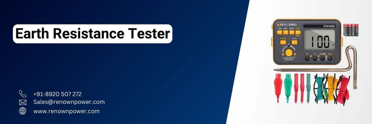
Earth Tester for earth resistance measurement: Introduction
Construction
The Earth Resistance Tester uses a hand-driven generator. The rectifier and the rotational current reverser are the two principal components of the Earth Tester. The rectifier converts AC (Alternating Current) into DC.
The Earth Tester works only on DC (Direct Current). The rectifier and current reverser have clambered on the shaft of the DC generator.
The tester has two commutators installed simultaneously with the current reverser and rectifier. Each commutator consists of four fixed brushes.
- Two pressure coils
- Two current coils
- A permanent magnet
- A DC generator
- Current reverser
- Rectifier
- Potential coil
- Analog resistance
- Indicator
Working of Earth Resistance Tester
The pressure and current coils have two-two terminals each. These pairs are placed across a permanent magnet. One synchronized pair of current and pressure coils are short-circuited, and connected to the ancillary electrodes.
The other pressure coil is connected to the rectifier at one end and an earthing electrode at another end. The current coil is too connected in a similar manner.
The potential coil is undeviatingly united to the DC generator. The potential coil is placed amidst the permanent magnet. This coil is connected to the pointer and the pointer is calibrated to the scale. This resistance pointer indicates the measurement of the earth’s resistance.
Note: The deflection of the pointer depends on the quotient of the voltage of the pressure coil to the current of the current coil.
The short-circuit passes the current to the soil. And hence the resistance is measured using Ohm’s Law which states,
V=IR;
Where V=voltage, I=current, and R=resistance.
How to use it?
The used method is a four-point method. The required pieces of equipment for the precise measurement are:
- Earth Tester (4 terminal).
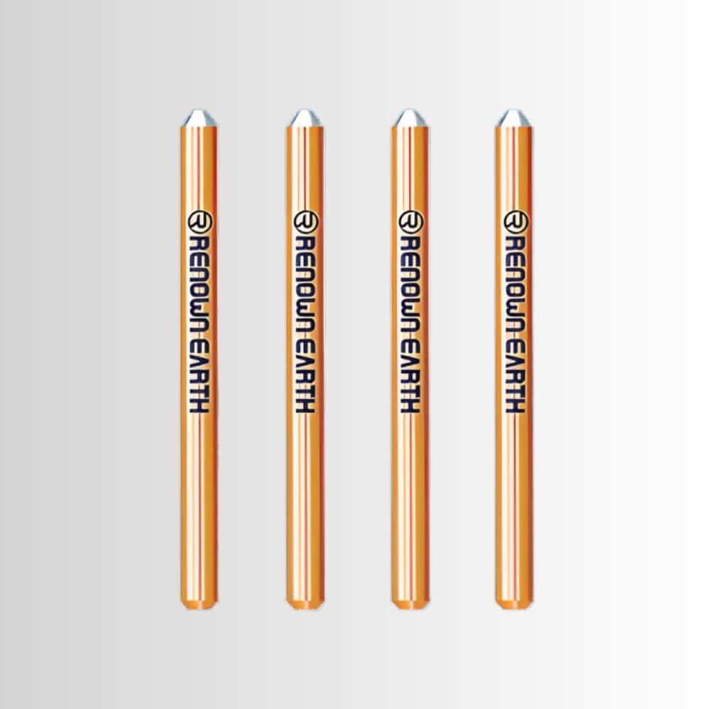
- 4 electrodes.
- 4 insulated wires.
- A hammer.
- Measuring tape
How to connect?: Procedure
Let us discuss the points to deliberate.
Firstly,
Take the grounding electrode and isolate it from the rest of the system for measurement.
Secondly,
Mark the current terminals of Earth Resistance Tester as C1 and C1 and potential centers as P1 and P2.
Thirdly,
Colorise the leads as per the standards as:
- C1=Black
- C2=Red
- P1=Green
- P2=Yellow
Fourthly,
Drive four small-sized electrodes into the soil at the same depth and equal distances from each other.
Note: The measure of electrode depth in the earth should be at least 20 times smaller than earthing electrodes.
Fifthly,
The earth electrode is connected to the C1 terminal of the Earth Resistance Tester.
Sixthly,
The electrode is connected to the rest of Earth Resistance Testers terminal and potential terminals as per the rules of the Four Point Method.
Press start on the Earth Resistance Tester to test the resistance. Record at least six values of resistance and take the average as the exact value of the resistance measured.
Clamp-on earth resistance tester
It is a tool or tester used to save time effectively. It works on the principle of Ohms law. Here the user does not have to have to disconnect the ground system to process measurement.
The clamp has the following parts connected with it:
- A transmitter coil, which implements the voltage, and
- Receiver coil, which measures the current
Hither resistance is calculated using Ohms Law.
Difference between Earth Resistance Tester and Megger
The table shows the difference between the two.
| Serial No. | Earth Resistance Tester | Megger |
|---|---|---|
| 01. | It measures low resistance. | It measures high resistance. |
| 02. | Can not be used to test the quality of insulation. | Can be used to test the quality of insulation. |
| 03. | Can not function above its specified voltage. | Can be used to test the quality of insulation. |
| 04. | It is used to measure the resistance of earthing pit. | It is used for measuring the insulation resistance of the motor winding cable, etc. |
| 05. | Its measurements are in Ohms. | Its measurements are in Mega Ohms. |


